EE Graduation Projects: Hardware Design of Huffman-Coding Algorithm (HCA)
Levels
Of
Abstraction
Branding
The four abstraction levels of a digital circuit design are shown in the figure.

A digital system is a sequential logic system constructed with flip‐flops and gates. Sequential circuits can be specified by means of state tables. To specify a large digital system with a state table is very difficult, because the number of states would be enormous. To overcome this difficulty, digital systems are designed via a modular approach. The system is partitioned into subsystems, each of which performs some function. The modules are constructed from such digital devices as registers, decoders, multiplexers, arithmetic elements, and control logic. The various modules are interconnected with datapaths and control signals to form a digital system. The modules of a digital system are best defined by a set of registers and the operations that are performed on the binary information stored in them. Registers are assumed to be the basic components of the digital system. The information flow and processing performed on the data stored in the registers are referred to as register transfer operations. A digital system is represented at the register transfer level (RTL) when it is specified by the following three components:
-
The set of registers in the system.
-
The operations that are performed on the data stored in the registers.
-
The control that supervises the sequence of operations in the system.

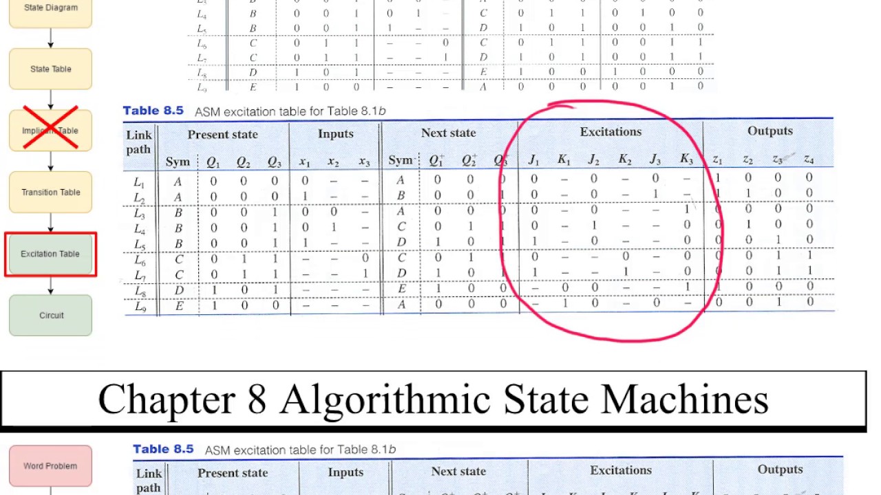
The control path is implemented using state machines which can be realized using state graphs. As the control path (behavior) of the system becomes complex, it becomes increasingly difficult to design the control path using the state graph technique. The Algorithmic State Machines (ASM) technique becomes useful in designing complex and algorithmic circuits. The following diagram shows a complex digital system, partitioned into a controller (control signals generator) and the controlled architecture (data processor).
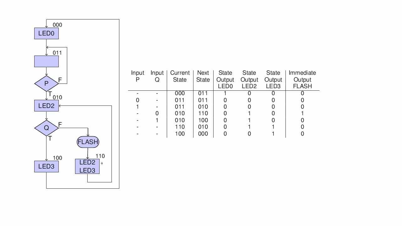
The ASM chart differs from an ordinary flowchart in that specific rules must be followed in constructing the chart. When these rules are followed, the ASM chart is equivalent to a state graph, and it leads directly to a hardware realization. The following diagram shows the three main components of ASM chart.
The state of the system is represented by a state box, which contains a state name, and it may contain an output list (just like in a state graph of the Moore machine). A state code may be placed outside the box at the top (if you want to assign a state code). A decision box always has true and false branches. The condition placed in the decision box must be a Boolean expression that is evaluated to determine which branch to take. The conditional output box contains a conditional output list. The conditional outputs depend on both the state of the system and the inputs (just like Mealy machine).
The ASM chart differs from an ordinary flowchart in that specific rules must be followed in constructing the chart. When these rules are followed, the ASM chart is equivalent to a state graph, and it leads directly to a hardware realization. The following diagram shows the three main components of ASM chart.